


Replacing a Single P4 256*128mm LED Module: What You Need to Know
Nov 12, 2025
Leave a message
Replacing a Single P4 256*128mm LED Module: What You Need to Know
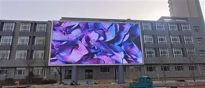
In Outdoor LED Display Systems, P4 Modules Are Widely Used in Scenarios Such as Billboards, Stage Backgrounds, and Traffic Information Screens Due to Their Balanced High Definition and Optimal Viewing Distance. When a 256×128mm Module Fails, Timely and Standardized Replacement Is Crucial for Ensuring Overall Display Quality and Prolonging Equipment Lifespan. This Article Provides a Comprehensive Guide on the Replacement Process for This Module Specification, Covering All Stages from Pre - Replacement Preparation to Post - Replacement Testing, Aiming to Offer Technicians a Complete and Rigorous Operational Reference.
I. Analysis of Basic Module Parameters
1.1 Meaning of P4 Pixel Pitch
The "P" in "P4" stands for Pixel, and the number "4" indicates that the distance between the centers of two adjacent pixels is 4 millimeters. This parameter directly influences the module's physical resolution and determines its optimal viewing distance. For P4 modules, the theoretical optimal viewing distance is approximately 4 to 40 meters, within which the image remains clear without noticeable pixelation.
1.2 Physical Dimensions and Pixel Count
The standard outdoor P4 module measures 256mm (width) × 128mm (height). Based on the pixel pitch:
Horizontal pixel count = 256 ÷ 4 = 64 pixels
Vertical pixel count = 128 ÷ 4 = 32 pixels
Thus, the resolution of a single module is 64×32, with a total of 2,048 pixels.
1.3 Explanation of 8 - Scan Driving Method
"8 - scan" refers to the module's 1/8 dynamic scanning driving method. At any given moment, only 1/8 (i.e., 4 rows) of the total rows are illuminated simultaneously, with high - speed rotation enabling full - screen visual display. This method effectively reduces power consumption and heat generation but imposes stringent timing requirements on the control system. During replacement, ensure the new module matches the original system's scanning method; otherwise, display abnormalities (e.g., uneven brightness, streaks, flickering) may occur.
1.4 Characteristics of 1921 LEDs
"1921" is a common outdoor LED package type, measuring approximately 1.9mm × 2.1mm (length × width) in a surface - mount device (SMD) three - in - one configuration (integrating red, green, and blue chips in a single package). Key features include:
- High brightness output, suitable for outdoor environments with strong ambient light.
- Good waterproof, dustproof, and UV - resistant properties.
- Wide viewing angles (typically ≥140° horizontally and vertically).
- High soldering reliability, compatible with automated assembly.
During replacement, verify that the new module's LED model, color temperature, and brightness level match the original screen to avoid color deviation or abrupt brightness differences.
II. Pre - Replacement Preparations
2.1 Safety Precautions
Outdoor LED screens are often installed at heights. Before starting work, implement the following safety measures:
- Cut off power to the entire screen or the affected area to prevent electric shock.
- Use safety belts, non - slip shoes, and helmets compliant with national standards.
- Avoid working in extreme weather conditions such as strong winds, thunderstorms, high temperatures, or low temperatures.
- Set up warning signs to prevent unauthorized personnel from entering the work area.
2.2 Tools and Materials Checklist
Required tools include:
- Cross - head screwdriver (matching module fixing screws; used to remove the screws securing the module).
- Antistatic wrist strap (to prevent electrostatic damage to ICs).
- Multimeter (for voltage and continuity testing).
- Hot air gun or soldering station (for handling soldering issues, if needed).
- Cleaning cloth and isopropyl alcohol (for cleaning interfaces).
- Spare module (preferably of the same model and batch).
- HUB cables, power cables (replace if damaged).
2.3 System Status Documentation
Before disassembly, record the following information:
- Physical coordinates of the faulty module in the entire screen (e.g., Row X, Column Y).
- Current control system version and receiving card configuration.
- Module back label information (including production date, batch number, scanning method).
- Interface type (e.g., HUB75) and cable routing.
This information aids in subsequent debugging and compatibility verification.
III. Module Disassembly Process
3.1 Power Disconnection and Signal Isolation
First, turn off the power switch for the corresponding area and unplug the module's power and data cables. If the module is part of a cascaded link, carefully note its upstream and downstream connections. This is crucial to avoid accidentally unplugging other modules, which could disrupt the entire display system.
3.2 Removal of Fixing Structures
Outdoor P4 modules are typically secured to the cabinet frame with four corner screws or clips. Use an appropriate screwdriver to remove the fixing screws, keeping them safe to prevent loss. Some designs feature quick - release mechanisms; press the release clips and gently remove the module.
3.3 Disconnection of Electrical Components
Carefully unplug the HUB cables and power connectors. When plugging or unplugging, hold the connector body and avoid pulling the cables to prevent damage to internal solder joints or poor contact. If cables are aged or oxidized, replace them.
3.4 Extraction of the Faulty Module
Support the module edges with both hands and withdraw it smoothly. Avoid excessive force to prevent loosening adjacent modules or scratching LEDs. After removal, inspect the backplate for signs of burning, bulging, or corrosion to help diagnose the fault cause.
IV. Installation Steps for the New Module
4.1 Appearance and Parameter Verification
Before installation, confirm the new module meets the following criteria:
Dimensions: 256×128mm.
Resolution: 64×32.
Scanning method: 8 - scan.
LED type: 1921.
Interface type matches the original module.
Surface free of scratches, missing LEDs, or cold solder joints.
4.2 Interface Cleaning and Inspection
Wipe the new module's data and power interfaces with isopropyl alcohol to remove grease or oxidation. At the same time, inspect the cable connectors for any signs of flatness or deformation.
4.3 Connection of Electrical Components
First, connect the HUB cables, ensuring correct orientation and a secure fit (gently pull to confirm). Then, connect the power cables, ensuring correct polarity (do not reverse). Some systems use dual power inputs; connect both if applicable.
4.4 Fixing the Module
Align the module with the cabinet mounting position and gently push it in until fully seated. Tighten the four corner screws evenly to avoid PCB board deformation or LED damage from excessive pressure. For clip - based designs, listen for a "click" sound indicating proper locking.
V. Power - On Testing and Debugging
5.1 Initial Power - On Observation
After restoring power, observe whether the new module lights up normally. It should display content consistent with surrounding modules. If the module remains entirely black, shows a distorted image, has partially dead areas, or flickers, immediately cut off power for troubleshooting.
5.2 Common Fault Diagnosis
Entirely Black and Unresponsive
Check power connection.
Verify voltage normalcy (typically DC5V ± 0.2V).
Inspect cable orientation and looseness.
Partially Dead Areas
Possible row/column driver IC failure or poor cable contact; inspect 8 - scan row selection signals.
Color Abnormalities (Red/Green/Blue Bias)
LED batch differences or data line short circuits; use a multimeter to test RGB signal line continuity.
Abnormally Low or High Brightness
New module lacks calibration coefficients, or drive current settings differ.
5.3 Control System Matching
If the new module is from a different batch, recalibrate its position - specific data (e.g., brightness, chromaticity correction coefficients) in the control system. Some advanced systems automatically identify module IDs and load corresponding parameters, but manual calibration remains recommended.
5.4 Burn - In Testing
After replacement, run the module continuously for over 24 hours to detect intermittent faults, overheating, or dead LEDs. Given outdoor temperature fluctuations, ensure stable operation under high/low - temperature cycles.
VI. Maintenance and Prevention Recommendations
6.1 Regular Inspections
Establish a routine inspection schedule to check for loose module fixing, interface oxidation, and cabinet seal integrity. Before and after the rainy season, pay special attention to the condition of waterproof seals and ensure that drainage holes are clear of any debris.
6.2 Spare Parts Management
Maintain an adequate stock of spare modules of the same model and batch, labeling them with production dates and parameters. Even if LED models match, batch differences may cause color variation; exercise caution when mixing batches.
6.3 Antistatic Practices
All operators must wear antistatic wrist straps and work on antistatic mats. LED module driver ICs are sensitive to electrostatic discharge (ESD); improper handling may cause latent damage, shortening lifespan without immediate detection.
6.4 Environmental Adaptability
Although outdoor P4 modules typically offer IP65 or higher protection, avoid prolonged exposure to chemically corrosive environments, sandstorms, or highly acidic rain. If necessary, install protective covers or regularly clean surface contaminants.
Why Choose Us as Your Trusted LED Display Partner?
With 15+ years of manufacturing experience, we are a leading LED display producer serving 60+ countries worldwide. Our core strengths include:
✅ OEM/ODM Support – Customized solutions tailored to your specific needs
✅ Certified Quality – All products meet international standards (CE, RoHS, ISO certified)
✅ Cost-Effective Production – Competitive pricing without compromising quality
✅ Global Logistics Network – Reliable shipping to all major markets
✅ R&D Innovation – Cutting-edge LED technology for superior performance
We specialize in indoor/outdoor LED screens, rental displays, and creative installations. From small batches to bulk orders, our flexible manufacturing capacity ensures timely delivery.
Let's build brilliant visual solutions together! Contact us today for a quote.
📱 WeChat: 86 18676738905
📧 Email: Ledhll88@163.Com
🌐 Website: Www.Hll-Ledscreens.Com
Send Inquiry