


Arctic-Grade LED Displays: How We Survived -50°C in Siberia
Jul 23, 2025
Leave a message
Arctic-Grade LED Displays: How We Survived -50°C in Siberia
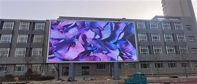
The winter temperatures in Siberia can plummet to below -50°C, posing severe challenges to the physical structure, electronic components, and optical performance of LED displays. To ensure the stable operation of equipment in such ultra-low-temperature environments, a systematic solution must be constructed from six dimensions: material selection, structural design, temperature control systems, power management, protective measures, and maintenance strategies.
I. Low-Temperature-Resistant Materials and Component Selection
1. Display Materials and Packaging Technology
Traditional liquid crystal materials solidify below -30°C, leading to a decline in response speed or even failure. For extreme-cold-grade LED displays, organic light-emitting diodes (OLEDs) or specially formulated liquid crystal materials are required to maintain fluidity at temperatures as low as -70°C. The packaging layer should employ high-hardness, anti-brittle composite materials with a matte or low-reflectance finish to reduce environmental light reflection while enhancing wear resistance. For example, the use of common-anode full-flip chip COB packaging technology, which directly solders LED chips onto the circuit board, eliminates the wire bonding process and prevents solder joint brittleness caused by low temperatures.
2. Structural Materials and Connectors
The display cabinet should be made of one-piece die-cast aluminum alloy, with a thermal expansion coefficient matching that of the LED module to prevent connection structure fractures due to thermal expansion and contraction. Floating interlocking connectors should be used between cabinets, eliminating the need for cable connections and reducing the risk of poor contact caused by low temperatures. An elastic buffer layer should be added at the connection between the module and the cabinet to absorb stress caused by temperature changes.
3. Cold-Resistant Electronic Components
The power module should utilize ultra-low-temperature electrolytic capacitors, whose dielectric remains liquid at -50°C to ensure stable capacitance. Critical components such as control cards and driver chips must pass -60°C low-temperature tests and adopt low-power designs to reduce heat generation. The PCB should employ a copper-clad laminate with a glass transition temperature of at least 150°C and undergo "three-proof" treatment (moisture, salt spray, and mold resistance) to prevent short circuits caused by low-temperature condensation.
II. Temperature Control System Design
1. Active Heating Devices
Electric heating sheets or films should be integrated inside the display, evenly distributed on the back of the modules and in the power compartment. Heating devices should monitor the ambient temperature in real-time through temperature sensors and automatically activate when the temperature drops below -20°C to maintain an internal temperature between -10°C and 0°C. The heating power should be dynamically adjusted according to the screen area, such as configuring 100-150W of heating power per square meter, to avoid localized overheating.
2. Thermal Management Structure
A fanless natural convection cooling design should be adopted, enhancing heat dissipation through the fin structure of the die-cast aluminum cabinet. Thermal grease should be filled between the module and the cabinet to ensure rapid heat conduction from the LED chips to the cabinet surface. Drain holes should be reserved at the bottom of the cabinet to prevent water accumulation from melting snow.
3. Intelligent Temperature Control Algorithm
An embedded controller should be used to achieve dynamic balance between heating and cooling. For example, when the ambient temperature rises to -10°C, the heating power should be automatically reduced; when the temperature reaches 5°C, the heating device should be completely turned off. Meanwhile, the temperatures of critical components such as the power supply and driver chips should be monitored to prevent overheating damage.
III. Power System Optimization
1. Ultra-Low-Temperature Power Design
The power module should support startup at -50°C, employing wide-temperature electrolytic capacitors and cold-resistant magnetic components. At -40°C, the power load should not be derated by more than 30% to ensure normal display illumination. A filtering circuit should be added at the power input to suppress electromagnetic interference caused by low temperatures.
2. Redundant Power Supply Architecture
A dual-power hot backup design should be adopted, with an automatic switching time between the primary and backup power supplies of no more than 5ms. The power compartment should be independently sealed to prevent snow infiltration. The power distribution system should employ a step-by-step power-on strategy to avoid inrush currents during full-screen startup. For example, the control card power supply should be started first, followed by the module power supplies in sequence.
3. Low-Power Drive Technology
Driver chips should support low-voltage startup (e.g., 4.2V) to reduce power conversion losses. A common-cathode design should be adopted to lower the operating voltage of LED chips through split power supply, reducing overall power consumption by more than 40% compared to traditional designs. For example, the peak power consumption should be ≤300W/m², and the average power consumption should be ≤100W/m².
IV. Strengthened Protective Measures
1. Snow and Ice Prevention
The display should be installed with a 5°-10° inclination angle to allow snow to slide off automatically by gravity. A snow guard should be added to the top of the cabinet to reduce snow accumulation. In extreme snowfall conditions, a spray system or snow scraper can be configured for automatic snow removal through remote control.
2. Wind and Dust Prevention
A windbreak should be installed on the back of the display to reduce vibrations caused by strong winds. The module gaps should be filled with sealing strips to prevent dust intrusion. The cabinet should have an IP65 protection rating to ensure normal operation in blizzard conditions.
3. Electrostatic and Lightning Protection
The metal frame of the display should be reliably grounded, with a grounding resistance of ≤4Ω. Operators should wear electrostatic wristbands to prevent electrostatic discharge from damaging LED chips. A surge protector should be added at the power input to prevent voltage surges caused by lightning strikes.
V. Maintenance Strategy Formulation
1. Regular Inspections and Cleaning
The heating devices and temperature sensors should be inspected monthly to ensure no aging or damage. The display surface should be cleaned of snow and dust every quarter using a soft brush or vacuum cleaner to avoid scratching the packaging layer. After cleaning, a brightness uniformity test should be conducted to ensure a grayscale loss of ≤5%.
2. Preheating Startup Mechanism
If the display has not been used for an extended period (e.g., more than 7 days), it should be restarted at 30%-50% brightness for 4-8 hours of preheating before adjusting to normal brightness. The preheating process can expel internal moisture to prevent short circuits caused by condensation.
3. Remote Monitoring and Fault Warning
Remote monitoring should be implemented through IoT technology to transmit parameters such as temperature, humidity, and voltage in real-time. When abnormalities are detected, the system should automatically send alerts to maintenance personnel's mobile phones and record fault logs. For example, events such as temperature sensor failures or power supply switching failures should be responded to within 5 minutes.
VI. Extreme Environment Adaptability Testing
1. Low-Temperature Storage Test
The display should be placed in a -60°C environment for 72 hours to detect issues such as material brittleness and solder joint detachment. After testing, it should pass a high-low temperature cycling test (e.g., -60°C to +70°C, 10 cycles) to ensure structural stability.
2. Low-Temperature Startup Test
The startup time of the display from shutdown to normal display should be tested at -50°C. The startup delay should be ≤2 minutes, with no screen flickering or flashing. The test should cover the entire chain, including the power supply, control card, and modules.
3. Lifespan Acceleration Test
Through alternating high-temperature and high-humidity (85°C/85%RH) and low-temperature and low-humidity (-40°C/10%RH) tests, a 10-year usage scenario should be simulated to verify the display's lifespan. The target mean time between failures (MTBF) should be ≥100,000 hours.
Why Choose Us as Your Trusted LED Display Partner?
With 15+ years of manufacturing experience, we are a leading LED display producer serving 60+ countries worldwide. Our core strengths include:
✅ OEM/ODM Support – Customized solutions tailored to your specific needs
✅ Certified Quality – All products meet international standards (CE, RoHS, ISO certified)
✅ Cost-Effective Production – Competitive pricing without compromising quality
✅ Global Logistics Network – Reliable shipping to all major markets
✅ R&D Innovation – Cutting-edge LED technology for superior performance
We specialize in indoor/outdoor LED screens, rental displays, and creative installations. From small batches to bulk orders, our flexible manufacturing capacity ensures timely delivery.
Let's build brilliant visual solutions together! Contact us today for a quote.
📱 WeChat: 86 18676738905
📧 Email: Ledhll88@163.Com
🌐 Website: Www.Hll-Ledscreens.Com
Send Inquiry